

As solar power systems scale up-for off-grid homes, RVs, boats, or large battery banks-a single charge controller often cannot handle the total power from expansive solar arrays. Parallel charging, where multiple solar charge controllers connect to the same battery bank, provides a flexible and effective solution. This approach boosts charging capacity, adds redundancy, and supports modular system growth.
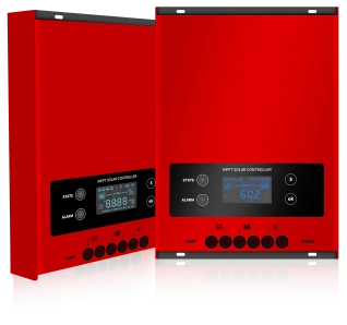
What Is Parallel Charging of Solar Charge Controllers?
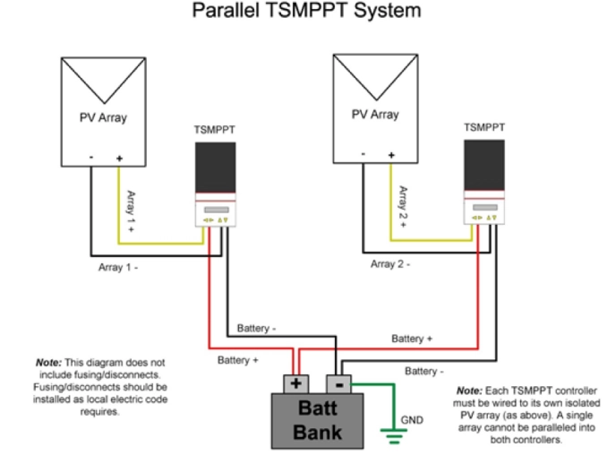
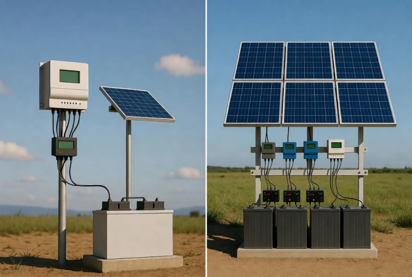
Parallel charging involves connecting the outputs of two or more charge controllers (typically MPPT or PWM) to a single battery bank. Each controller manages its own dedicated solar array (PV sub-array), while their DC outputs tie together at the battery side, usually via busbars.
This setup differs from simply paralleling solar panels into one controller. Here, each controller independently optimizes its array via MPPT or PWM, then delivers power collectively to the batteries.
2. Core Parallel Working Principle
Multiple controllers connect independent photovoltaic strings respectively, share the same battery bank, and realize current sharing & synchronous charging stage switching via RS485 communication.
PV side: Independent access for each controller
Battery side: All controllers connect to the same battery busbar
Communication side: Daisy-chain RS485 wiring for synchronous control
Why Use Multiple Charge Controllers in Parallel?
Increased Charging Capacity: Combine currents (amps) from multiple units while maintaining system voltage.
Modular and Scalable Design: Easily expand by adding arrays and controllers.
Redundancy and Reliability: If one controller or array fails, others continue charging.
Better Performance with Varied Conditions: Separate arrays can face different orientations, tilts, or shading. Each controller optimizes independently.
Voltage Flexibility: Different array voltages are possible as long as each matches its controller's input specs.
3. Preparations & Wiring Steps
Required Tools & Materials
Insulating gloves, multimeter, DC clamp meter, shielded twisted pair RS485 cable, PV cables, battery main cables, circuit breakers & fuses
Standard Wiring Sequence
Connect battery terminals first, then PV terminals, finally communication lines
Battery parallel connection
Connect B+ and B- of all controllers to unified battery positive & negative busbars; adopt star wiring, keep cables same length, fasten terminals tightly, install main circuit breaker and fuse on battery side.
Independent PV connection
Match each controller with exclusive PV string; ensure PV voltage and power are within controller rated range; equip separate circuit breaker for each PV branch.
RS485 daisy-chain communication wiring
Connect A to B, B to C in sequence; switch on 120Ω terminal resistors on the first and last controller; single-end ground the shield layer of communication cables, keep away from high-voltage power lines to avoid interference.

4. Unified Parameter Settings
Uniform basic parameters for all controllers
Battery voltage level(48V/24V/12V), bulk charging voltage, float charging voltage, low voltage recovery value, battery type (lead-acid/lithium battery) must be fully consistent.
Set exclusive communication address for each unit (1,2,3...)
Uniform baud rate (default 9600)
Enable parallel mode on all controllers; automatic current sharing is supported, no need to manually set master-slave mode in most models.
|
Parameter Name |
Default Value |
Setting Range |
|
ADDR (Communication ID) |
1 |
Custom: 1~200, fine step 1, coarse step 10.Must be set for parallel communication, and each parallel controller must have a unique address.Note: The setting range is 1-15 when operating in parallel. |
|
BT (Battery Type) |
AGM |
48V System Range: AGM (Maintenance-free), GEL , FLD , LFP15S, LFP16S , LNCM13S, LNCM14S , USER (Custom)24V System Range: AGM (Maintenance-free), GEL, FLD , LFP8S , LNCM6S , LNCM7S , USER (Custom)12V System Range: AGM (Maintenance-free), GEL, FLD, LFP4S, LNCM3S , USER (Custom) |
|
RVL (System Rated Voltage Level) |
0 |
Custom: 0 (Auto-detect), 12V, 24V, 48V |
|
PMCC (Parallel Max Charging Current) |
1200 A |
Limits the total charging current in parallel systems.Custom: 100~1200A, fine step 10A, coarse step 100A. |
Power-On Sequence
Switch on battery main power supply to start all controllers
Confirm all units display "Parallel OK" for normal communication
Switch on PV branch breakers one by one to start charging
5. Key Specifications & Forbidden Operations
Never connect one set of PV strings to two or more controllers, which will cause circulation current and device burnout.
Keep batteries highly consistent; forbid mixed use of old & new batteries or different-brand batteries; lithium battery system must match BMS charging parameters strictly.
Total charging current shall not exceed battery maximum charging current; select cable specification with 25% current margin, ensure firm and waterproof wiring terminals.
Only dual RS485 port models support parallel connection; missing terminal resistors will lead to unstable communication and unbalanced current distribution.
Equip independent maintenance switch for each PV branch, install short-circuit protection fuse on battery main circuit.
Regular inspection: check terminal temperature, system voltage, operating current and communication status; normal current difference between paralleled units shall be within 5A.
6.Electrical parameters
|
Technical Data |
||||||||
|
DS Series |
48L40 |
48L50 |
48L60 |
48H50 |
48H60 |
48H80 |
48H100 |
|
|
Controller Type |
Controller with Maximum Power Point Tracking (MPPT) function |
|||||||
|
MPPT Efficiency |
≥99.5% |
|||||||
|
No-load Static Power Loss |
1W~1.5W |
|||||||
|
System Voltage |
12V/24V/36V/48V Auto-detection |
|||||||
|
Cooling Method |
Air Cooling |
|||||||
|
Input Characteristics |
||||||||
|
PV Maximum Open Circuit Voltage |
150Vdc |
200Vdc |
250Vdc |
|||||
|
Charging Start Voltage Threshold |
3V above battery voltage |
|||||||
|
Input Low Voltage Protection Threshold |
2V above current battery voltage |
|||||||
|
Input Over Voltage Protection Threshold |
150Vdc |
200Vdc |
250Vdc |
|||||
|
Solar Panel Rated Input Power |
12V System |
520W |
650W |
780W |
650W |
780W |
1040W |
1300W |
|
24V System |
1040W |
1300W |
1560W |
1300W |
1560W |
2080W |
2600W |
|
|
36V System |
1560W |
1950W |
2340W |
1950W |
2340W |
3120W |
3900W |
|
|
48V System |
2080W |
2600W |
3120W |
2600W |
3120W |
4160W |
5200W |
|
|
Charging Characteristics |
||||||||
|
Applicable Battery Type |
Lead-acid Battery / Lithium-ion Battery |
|||||||
|
Lithium Battery Activation Function |
Optional |
|||||||
|
Rated Charging Current |
40A |
50A |
60A |
50A |
60A |
80A |
100A |
|
|
Charging Mode |
Lead-acid battery: Boost charge, Equalization charge, Float charge; Lithium battery: Boost charge, Equalization charge |
|||||||
|
Load Characteristics |
||||||||
|
Load Voltage |
Same as battery voltage |
|||||||
|
Rated Load Current |
30A |
50A |
||||||
|
Load Control Mode |
Normally Open/Normally Closed Mode, Dual Time Segment Control Mode, Light Control Mode, Light Control-Fixed Time Control Mode |
|||||||
|
Display & Communication |
||||||||
|
Display Mode |
High-definition LCD Segment Code Backlight Display |
|||||||
|
Communication Mode |
8-pin RJ45 Interface / RS485 / Support Upper Computer Monitoring / Support External Bluetooth, WIFI Module Expansion for APP Cloud Monitoring / Support External Monitoring Meter Head |
|||||||
|
Other Attributes |
||||||||
|
Protection Functions |
Input/Output Over/Under Voltage Protection, Reverse Polarity Protection, Battery Disconnection Protection, etc. |
|||||||
|
Operating Ambient Temperature |
-20℃~+50℃ |
|||||||
|
Storage Temperature |
-40℃~+70℃ |
|||||||
|
IP Protection Level |
IP21 |
|||||||
|
Maximum Wiring Size |
20mm² |
25mm² |
||||||
|
Net Weight (kg) |
1.7 |
3.4 |
||||||
|
Gross Weight (kg) |
2.1 |
4 |
||||||
|
Product Dimensions (mm) |
240*166*65 |
305*200*85 |
||||||
|
Package Dimensions (mm) |
292*204*67 |
382*245*129 |
||||||
Summary
Parallel installation requires matching applicable models, separate PV access and shared battery connection. Standardize daisy-chain communication wiring and unified parameter configuration to ensure balanced current output. Strictly follow wiring and power-up procedures, avoid incorrect wiring and mismatched battery combination. Conduct routine inspection and fault troubleshooting to guarantee stable, safe and long-term system operation.If necessary, please contact us immediately.