Abstract
Module mismatch is one of the core technical bottlenecks restricting the improvement of photovoltaic (PV) system power generation efficiency. Its essence is the "bucket effect" caused by inconsistent output currents of PV modules in a series circuit. According to statistics from the International Energy Agency (IEA) Photovoltaic Power Systems Programme (PVPS), the global average power generation loss due to mismatch in PV power plants ranges from 5% to 15%, and can even exceed 20% in plants with complex terrain or poor operation and maintenance. Among them, tilt angle difference is the most dominant cause of mismatch in complex installation scenarios such as mountainous areas and rooftops, accounting for approximately 40%-60% of total mismatch losses.

1. Basic Principles and Physical Mechanisms of PV Module Mismatch
1.1 Electrical Characteristics of PV Modules
The output characteristics of a PV module are determined by its current-voltage (I-V) curve and power-voltage (P-V) curve. Under Standard Test Conditions (STC: irradiance 1000W/m², cell temperature 25°C, AM1.5 spectrum), a single module has a unique Maximum Power Point (MPP).
The short-circuit current (Isc) of a PV module is approximately proportional to the solar irradiance incident on the cell surface, which is the core physical basis for current mismatch caused by tilt angle differences. The formula is expressed as:
Isc ≈ Isc_STC ×(G/GSTC)
Where:
• Isc: Actual short-circuit current (A)
• Isc_STC: Short-circuit current under standard test conditions (A)
• G: Actual incident irradiance (W/m²)
• G_STC: Standard test irradiance (1000W/m²)
When multiple modules are connected in series to form a string, according to Kirchhoff's Current Law, all modules in a series circuit must operate at the same current; while the total voltage of the string is equal to the sum of the operating voltages of each module. This characteristic determines that series systems are extremely sensitive to current differences.

1.2 Core Mechanism of the Mismatch Phenomenon
The "barrel effect" (also known as the "weakest link" or "bottleneck effect") is a perfect analogy for what happens in series-connected PV modules. Imagine a series of barrels connected in a chain, each with a different capacity. The amount of water that can flow through the entire system is limited by the barrel with the smallest capacity-regardless of how large the others are.

In a PV string, modules are electrically connected in series, meaning the same current must flow through all of them. The module receiving the least irradiance (due to a suboptimal angle) will generate the lowest current. This forces the entire string's current to match the lowest performer, causing the higher-performing modules to operate below their potential. Power losses can be substantial, far exceeding the simple sum of individual reductions.

2. Main Causes of PV Module Mismatch
The causes of module mismatch are complex and diverse, and can be divided into two categories: congenital mismatch and acquired mismatch.
2.1 Congenital Mismatch: Factory Parameter Differences
Even modules produced in the same batch have slight differences in their electrical performance parameters due to factors such as semiconductor material purity and production process fluctuations. Module manufacturers usually perform power grading (binning) on modules, but modules within the same power bin may still have current differences within ±2.5%.
The mismatch loss caused by such factory parameter differences is usually 2%-3%, which is a basic mismatch loss that cannot be completely avoided in all PV systems.

2.2 Acquired Mismatch: Operating Environment and Operation & Maintenance Factors
This is the main reason why the actual system mismatch loss is much larger than the basic value, specifically including:
• Inconsistent tilt angles and azimuth angles (will be analyzed in depth below)
• Shading mismatch: Fixed shading from surrounding buildings, trees, mountains, etc., and dynamic shading from clouds, birds, etc.
• Soiling and aging mismatch: Uneven soiling such as dust, snow, bird droppings on the module surface, and differences in aging rates after long-term operation
• Temperature mismatch: Uneven temperatures caused by different heat dissipation conditions of modules

3. In-depth Mechanism and Quantitative Analysis of Mismatch Caused by Tilt Angle Differences
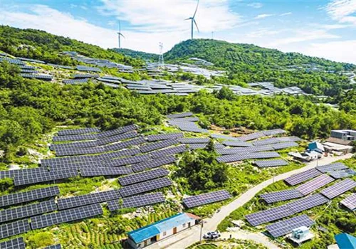
Tilt angle mismatch refers to the inconsistent installation tilt angles (the angle between the module plane and the horizontal plane) of different modules in the same series string, resulting in different amounts of solar irradiance received by each module, and thus differences in output current. This is the most common and easily overlooked type of mismatch in mountainous PV and distributed rooftop PV systems.
3.1 Key reasons installation angle differences exacerbate this:
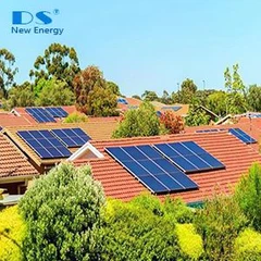
• Irradiance Variation: A module tilted at a different angle captures less direct sunlight, especially during peak hours. For example, on a sloped roof with varying pitches, south-facing modules at optimal tilt might perform well, while others at shallower or steeper angles underperform.
• Daily and Seasonal Impact: Angles affect not just peak output but performance across the day. Non-uniform tilts lead to mismatched IV curves (current-voltage characteristics), increasing mismatch losses.
• Compounding with Other Factors: Angle differences can worsen shading effects or temperature gradients, as poorly angled modules may heat differently.

3.2 Quantitative Correlation Between Tilt Angle Difference and Module Output Current
We can quantify the relationship between tilt angle difference and current difference by accurately calculating the total plane irradiance at different tilt angles. Taking the 30°N latitude region (the Yangtze River Basin in China) as an example, the following table shows the annual total irradiance and short-circuit current differences for different installation tilt angles relative to the optimal tilt angle (approximately 30°):
Installation Tilt Angle (°) | Annual Total Irradiance (kWh/m²) | Irradiance Difference Relative to Optimal Tilt Angle (%) | Short-Circuit Current Difference (%) |
| 10 | 1285 | -12.3 | -12.3 |
| 15 | 1352 | -7.7 | -7.7 |
| 20 | 1401 | -4.4 | -4.4 |
| 25 | 1432 | -2.3 | -2.3 |
| 30 (Optimal) | 1466 | 0 | 0 |
| 35 | 1451 | -1.0 | -1.0 |
| 40 | 1420 | -3.1 | -3.1 |
| 45 | 1373 | -6.3 | -6.3 |
| 50 | 1312 | -10.5 | -10.5 |
Key Conclusions:
1. In the 30°N latitude region, for every 5° deviation from the optimal tilt angle, the annual irradiance decreases by approximately 2%-4%, corresponding to a 2%-4% decrease in short-circuit current.
2. When the tilt angle difference reaches 20° (e.g., 30° vs 10°), the annual current difference can exceed 12%.
3. Instantaneous current differences are much larger than annual average differences. For example, at noon on the summer solstice, the solar altitude angle is approximately 83.5°, at which time the direct irradiance received by a module with a 10° tilt angle is about 15% higher than that received by a module with a 30° tilt angle; while at noon on the winter solstice, the solar altitude angle is approximately 36.5°, and the direct irradiance received by a module with a 10° tilt angle is about 25% lower than that received by a module with a 30° tilt angle.
4. Comparison of Mainstream Solutions for Module Mismatch
Aiming at the module mismatch problem, various solutions have been developed in the industry, whose core idea is to break the restriction that "series currents must be consistent" or minimize current differences.
4.1 Special Design Optimization for Tilt Angle Mismatch
This is the most basic and lowest-cost solution, and also the measure that all projects should first adopt:
1. Strictly implement the "same tilt angle, same string" principle: This is the golden rule for preventing tilt angle mismatch. Modules with the same tilt angle and azimuth angle should be connected in series in the same string, and modules with different tilt angles/orientations must never be connected in series together.
2. Reasonably shorten string length: In areas with large tilt angle differences, appropriately shortening the string length (from 22-24 modules to 18-20 modules) can reduce the impact range of mismatch.
3. Optimize inverter MPPT channel division: Connect strings from different tilt angle zones to different MPPT channels, so that each MPPT channel only tracks the maximum power point of strings with the same tilt angle.

4.2 String Inverter: Multi-MPPT Inverters
Traditional central inverters usually have only 1-2 MPPT channels, while modern string inverters are generally equipped with multiple independent MPPT channels (6-12 or even more). Each MPPT channel can independently track the maximum power point of different strings, thus limiting the impact of mismatch to a single MPPT channel.
Effect on tilt angle mismatch: Can effectively solve the mismatch problem between different tilt angle zones, but still cannot solve the tilt angle differences within strings in the same zone.

4.3 Module-Level Power Electronics (MLPE) Technology
This is currently the most effective technical solution for solving tilt angle mismatch, mainly including power optimizers and microinverters:
1. Power Optimizer
Power optimizers are installed on the back of each module, corresponding one-to-one with the modules. It can independently adjust the operating voltage and current of each module, making each module work at its own maximum power point, and then output direct current to the series circuit.

Effect on tilt angle mismatch: Can completely eliminate current mismatch caused by any tilt angle difference within the string, allowing each module to output its maximum current. Measured data shows that in mountainous power plants with large tilt angle differences, the use of power optimizers can increase power generation by 15%-20%.
2. Microinverter
Microinverters are directly installed on the back of each module, converting the direct current output by the module directly into alternating current, which is then connected in parallel to the grid. Each module is an independent power generation unit, completely free from series current restrictions.
Effect on tilt angle mismatch: Completely solves all tilt angle mismatch problems, and each module can work independently regardless of the tilt angle difference.

Our company can provide all of the solutions and complete systems mentioned above. If you need them, please contact us!
With the continuous advancement of PV technology, solutions to the module mismatch problem are also constantly innovating and developing:
1. Higher efficiency MLPE technology: The conversion efficiency of new-generation power optimizers and microinverters has exceeded 99%, with further reduced self-power consumption and continuously declining costs.
2. Smart module technology: Integrating power optimizers or microinverters with modules to form smart modules, simplifying the installation process and improving system reliability.
3. Digital twin technology: Using digital twin technology to build a virtual model of the PV power plant, accurately simulating mismatch losses under different working conditions, and realizing early warning and optimal control.
4. New battery technology: Such as shingled modules, half-cut modules, sliced modules, etc., reduce the impact of shading and mismatch through cell segmentation and optimized connection methods. For example, half-cut modules can reduce power loss caused by shading by approximately 50%.
Module mismatch is an inevitable phenomenon in PV systems, among which tilt angle difference is the main cause of mismatch in complex installation scenarios, and the resulting power generation loss can reach more than 15%. Tilt angle differences directly lead to inconsistent output currents of modules by affecting the amount of solar irradiance received by the modules, and then limit the power generation of the entire string through the "bucket effect" of the series circuit.
For different types of PV power plants, the most appropriate mismatch solution should be selected according to factors such as terrain conditions, tilt angle difference size, and investment budget. Ground-mounted power plants can give priority to multi-MPPT string inverters; for complex scenarios such as mountainous areas and rooftops with large tilt angle differences, module-level power electronics technology will bring significant power generation improvements and investment returns.