
1. Basic Definition & Aliases
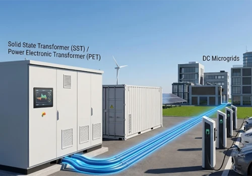
Solid State Transformer (SST), academically named Power Electronic Transformer (PET), also known as intelligent solid-state substation or energy router in the industry.
Essentially not an iron-core transformer, it is a modular power electronic device integrating rectification, inversion, high-frequency isolation and power quality regulation. It relies on SiC/GaN wide-bandgap semiconductors to realize voltage transformation and isolation via high-frequency switching, abandoning the traditional 50 Hz power-frequency iron-core structure.
The term "solid-state" indicates no rotating parts or oil-immersed iron cores; the whole device consists entirely of solid-state semiconductor components, distinguishing it from liquid oil-filled power-frequency transformers.

2. Working Principle
Derived from the electromagnetic induction formula:

The cross-sectional area of the iron core S is inversely proportional to operating frequency f.
Traditional power-frequency transformers operate at fixed 50 Hz, requiring bulky iron cores.
SST boosts the operating frequency to 20 kHz ~ 200 kHz, shrinking the volume of magnetic components to 1/10 ~ 1/5 of the original size for miniaturization.
Mainstream three-stage power conversion chain:
AC power frequency high-voltage alternating current → controlled rectification → high-voltage DC bus
High-voltage DC inverted into high-frequency alternating current → isolated voltage transformation by compact high-frequency transformer
High-frequency AC on the secondary side rectified/inverted → low-frequency AC or high-voltage DC output
Technical Data
|
Parameter |
Value |
|
Operating Temperature Range |
0°C~40°C |
|
Storage Temperature Range |
-40°C~+70°C |
|
Altitude |
2000m |
|
Operating Relative Humidity |
≤90%(40°C±2°C) |
|
Storage Relative Humidity |
≤95%(40°C±2°C) |
|
Peak Efficiency |
98.5% |
|
Overall Dimensions |
W6000mm*D1600mm*H2400mm |
|
Rated Power |
3MW |
|
Input Frequency |
50Hz/60Hz |
|
Input Voltage Range |
-15%~+10% |
|
Maximum Input Current |
108A |
|
Output Voltage |
800Vdc |
|
Output Voltage Accuracy |
±1% |
|
Overload Capacity |
105% continuous / 110% 60min / 125% 10min |
|
Low-Voltage Hot-Swap Function |
Yes |
|
Cooling Method |
Forced Air Cooling |
|
Operation Interface |
Human-Machine Interface (HMI) |
|
Communication Interface & Protocol |
RS485/Ethernet; Modbus RTU/Modbus TCP |
3. Three Main Commercial Topologies
(1) Three-stage Topology (Industrial Mainstream, Full-function Type)
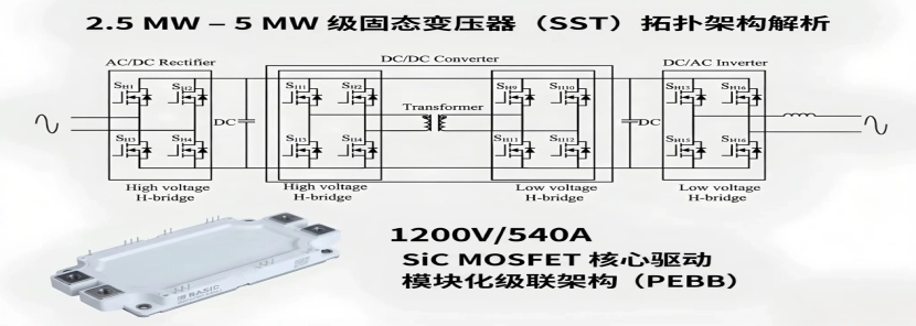
Structure: AC/DC Rectifier Stage + DC/DC High-frequency Isolation Stage + DC/AC Inverter Stage
Input stage: Cascaded H-bridge (CHB) / MMC multi-level rectification adapts to 10 kV & 35 kV medium-voltage grids, implementing power factor correction and harmonic suppression;
Isolation stage: DAB (Dual Active Bridge) / CLLC resonant converter (gradually replacing DAB for full-load soft-switching and lower loss) + high-frequency nanocrystalline magnetic core transformer;
Output stage: capable of AC output or 800 V DC bus output.
Advantages: DC buses exist on both high & low voltage sides, enabling bidirectional power flow, simultaneous harmonic suppression, energy storage access, and adaptation to AC-DC hybrid power grids.
Applications: 10 kV distribution substations, power supply for AI computing centers, integrated photovoltaic-storage-charging stations.
(2) Two-stage Topology (Lightweight Low-cost Scheme)
Two types: DC bus on high-voltage side or DC bus on low-voltage side. Structure: AC/DC rectification + single-stage isolated DC/DC conversion.
The post-stage inverter is omitted to output DC directly, featuring simpler structure and lower loss.
Drawback: grid disturbances easily couple to the low-voltage side, weak power quality regulation capacity.
Applications: EV ultra-fast charging piles, distributed industrial energy storage, low-voltage microgrids.
(3) Single-stage Matrix AC-AC Topology (Cutting-edge laboratory technology, not commercialized)
No intermediate DC capacitors. Matrix converter directly converts power-frequency AC into high-frequency AC, then restores power-frequency AC after passing the high-frequency transformer.
Minimal components and theoretically highest power density. However, without DC buffer links, grid fluctuations tend to break down power devices, and control algorithms are extremely complex. Only verified in aerospace research.
4. Core Hardware Composition
Power Semiconductors: Mainstream devices are 1200 V / 1700 V SiC MOSFETs; 3.3 kV SiC chips serve 35 kV high-voltage scenarios. Silicon-based IGBTs are phased out from medium-voltage SST due to high switching loss.
High-frequency Magnetic Components: Nanocrystalline, amorphous alloy, Mn-Zn ferrite cores (replacing silicon steel sheets) with ultra-low high-frequency loss.
Control System: Dual-core DSP+FPGA architecture for voltage/current sharing, millisecond-level voltage regulation and fault blocking.
Cooling System: Immersion liquid cooling / plate water cooling for high-power models; air cooling for small & medium units.
Modular Unit: Industry-standard ISOP (Input Series Output Parallel) modular architecture. Low-voltage SiC units are connected in series to withstand 10 kV high voltage; faulty modules can be bypassed without system shutdown.

5. Comparison: Solid State Transformer vs Traditional Power-frequency Transformer
|
Comparison Item |
Traditional Oil-immersed Power-frequency Transformer |
Solid State Transformer (SST) |
|
Operating Frequency |
50 Hz power frequency |
20 kHz ~ 200 kHz high frequency |
|
Volume & Weight |
100 kVA unit: ~500 kg, 1 m³ |
Same power: \50 kg, 0.1 m³, volume reduced by 80%\90% |
|
Functional Capacity |
Fixed turns-ratio voltage transformation only, passive component |
Integrates transformer + SVG reactive power compensation + APF active filter + UPS + fault protection |
|
Response Speed |
Tap-changer voltage regulation (second-level), fault protection >10 s |
Electronic regulation; voltage regulation / fault lockout: microsecond ~ millisecond level |
|
Power Flow |
Unidirectional power transmission, no reverse power feed |
Bidirectional power flow, supports V2G and reverse energy feedback from storage |
|
DC Compatibility |
Cannot connect DC directly, additional inverters required |
Native DC input & output, directly connects PV systems and 800 V computing buses |
|
Safety & Insulation |
Oil immersion, risk of oil leakage, fire & explosion |
Dry insulation / flame-retardant coolant, fire-proof |
|
Full-load Efficiency |
99.2% ~ 99.7% |
97% ~ 98.5% (close to power-frequency transformers under heavy load, lower efficiency under light load) |
|
Initial Cost |
Low, mature technology |
3~6 times the cost of power-frequency transformers |
|
Service Life |
Over 30 years with low maintenance |
15~20 years, limited by aging power devices |
6. In-depth Application Scenarios
(1) New Power System & Power Grid Side
Flexible solid-state substation
Replaces outdated box-type transformers in cities. A single SST integrates voltage regulation, three-phase unbalance treatment, harmonic filtering and fault isolation, solving problems such as frequent low voltage and excessive neutral current in old residential districts. It isolates faults within 0.8 seconds, while traditional transformers take more than 12 seconds.
Offshore wind power booster platforms
Offshore platforms feature limited space and high construction costs. SST cuts volume by 70%, eliminating large power-frequency transformer cabins to reduce offshore engineering construction and hoisting costs. DC output from offshore wind turbines can be directly connected to SST for step-up transmission.
Off-grid microgrids
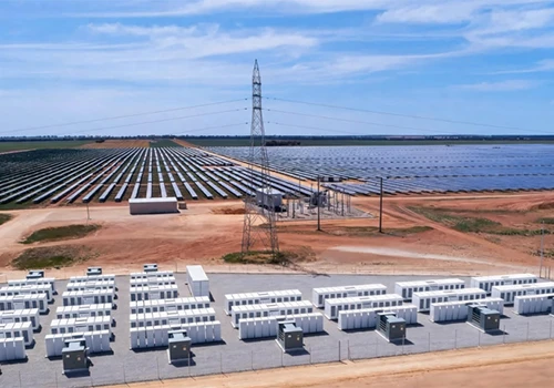
For remote islands, border outposts and field photovoltaic bases, PV + energy storage + SST forms containerized off-grid power systems to automatically stabilize intermittent photovoltaic output fluctuations.
(2) Computing Centers & Data Centers (Fastest commercialized track)
SST becomes the standard 800 V high-voltage DC power supply solution for NVIDIA & Huawei AIDC clusters. 10 kV municipal power connects to SST directly and converts into 800 V DC for GPU cabinets.
Eliminates 5-stage conversion links (10 kV box transformer → 400 V AC UPS → multi-stage rectification), raising overall power supply efficiency from 91% to 97.5%.
Cable current drops sharply, copper consumption cut by 55%, allowing 30% more computing cabinets deployed in data halls.
Built-in energy storage interfaces connect batteries to DC buses for seamless power switching and zero computing downtime during blackouts.
Pilot projects are running in Guian East-data West-computing Cluster, Tencent Qingyuan Computing Base and Alibaba Zhangbei Computing Park.

(3) Transportation Industry
On-board traction transformers for high-speed trains & EMUs
Replacing on-board power-frequency traction transformers with high-frequency SST reduces vehicle weight by 40%, lowering wheel-rail wear and train energy consumption. Electric energy regenerated during braking can be fed back to the grid or supplied to adjacent trains, cutting overall power consumption by 10%~15%.
Flexible power supply for metro systems
Metro lines in Guangzhou and Shenzhen carry out SST traction power supply pilots to eliminate harmonic pollution caused by metro operation and recycle braking energy, halving the floor area of metro substations.
Port shore power for ships
Ships worldwide adopt different voltage & frequency standards (6 kV/10 kV, 50 Hz/60 Hz). SST adapts to arbitrary voltage and frequency to realize seamless grid connection for ships of various countries and avoid grid-connected surges damaging ship power systems.

(4) Industrial Precision Power Supply
Wafer fabrication & lithography workshops for semiconductor industry
Lithography and etching equipment are extremely sensitive to voltage disturbance; a 0.5% voltage fluctuation will cause wafer scrapping. SST actively isolates lightning strikes and arc disturbances from the grid, supplying clean power with total harmonic distortion (THD) < 2%.
Metallurgical arc furnaces & large-scale industrial energy storage
Steel plants store electricity during off-peak hours and discharge during peak periods. Combined with SST bidirectional conversion for high-voltage energy storage, industrial electricity expenditure is reduced.
7. Industrialization Bottlenecks
Cost Barrier
High-voltage SiC power modules remain expensive. The overall cost of a 10 kV SST is 3~6 times that of an equal-capacity power-frequency transformer, lacking economic benefits for ordinary residential distribution networks.
High-frequency Insulation Challenge
High-frequency electric fields easily trigger partial discharge, accelerating aging of insulating materials under high voltage and limiting overall service life, the biggest technical difficulty for high-voltage SST.
Weak Short-circuit Withstand Capacity of Devices
Power-frequency transformers sustain several seconds of short-circuit impact, while SiC semiconductors burn out within microseconds under short-circuit conditions. Multi-redundant protection and bypass modules must be installed in control systems, increasing system complexity.
Poor Light-load Efficiency
When load is lower than 30% rated power, switching loss dominates SST power loss and efficiency drops below 93%. In contrast, power-frequency transformers maintain efficiency above 98% under light load, making SST unsuitable for rural distribution stations with persistently low loads.
Immature Operation & Maintenance System
Traditional transformers possess mature and widespread maintenance systems. SST integrates power electronics, embedded control and high-frequency magnetic technology, imposing higher technical requirements on maintenance personnel.
8. Future Development Trends
Device Upgrade: Gradual adoption of 3.3 kV & 6.5 kV high-voltage SiC devices reduces the number of series-connected units and simplifies the structure of 10 kV/35 kV SST; GaN devices penetrate high-power medium-voltage applications.
Topology Iteration: CLLC resonant topology replaces DAB comprehensively to solve the problem of high DAB loss under light load. Once control difficulties are solved, single-stage AC-AC topology will be applied in lightweight aerospace scenarios.
High Integration: Power, drive and sensor components are packaged into integrated SiC IPEM modules to further reduce device volume.
Application Differentiation
Ordinary urban & rural distribution networks will retain traditional power-frequency transformers;
Computing centers, ultra-fast charging stations, offshore wind power and rail transit will witness large-scale SST popularization from 2028 to 2032.
Networking Application: Multiple SSTs form an energy internet cluster to coordinate photovoltaic, energy storage and charging loads within regional power grids.