
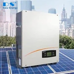
Inverters play a crucial role in photovoltaic power generation systems, converting the direct current (DC) generated by photovoltaic panels into alternating current (AC) suitable for grid connection or load use. The development of inverter technology has been constantly evolving to meet the requirements of higher efficiency, better power quality, and lower cost. Three - level inverter technology is one of the important advancements in this field.
The level concept in inverters refers to the voltage level used for signal transmission or energy conversion. A two - level inverter has only two voltage levels, high and low, which is simple in design and suitable for low - cost applications. However, three - level inverters introduce a voltage mid - point, providing three voltage levels, which allows for finer voltage control and has several significant advantages at the system level1.

1.The meaning of three-level technology
In the 1980s, Japanese scholar Nabae proposed a three-level inverter circuit based on diode clamping. Its typical topological structure is shown in the following figure. Each bridge arm of the entire inverter circuit is composed of 4 Insulated Gate Bipolar Transistors (IGBTs) and 6 diodes.

Although the three-level circuit is relatively more complex in topology, compared with the traditional two-level inverter circuit which can only output high and low levels, this novel inverter circuit can output high and low levels through the turn-on of the upper and lower tubes, and output zero level through the clamping effect of the intermediate diode, totaling three level states. Therefore, it is called a three-level inverter circuit.
Take the potential change at the midpoint of the inverter bridge arm of Phase A in the following figure as an example to briefly describe the specific meaning of the three levels.

- When the two IGBTs on the A-phase bridge arm are conducting, the potential at point A is the same as that of the positive bus, which is U/2. The stress platform voltage that each IGBT bears is U/2, as shown in Loop 1.
- When the two IGBTs of the lower bridge arm of the A-phase bridge arm are conducting, the potential at point A is the same as the negative bus potential, which is -U/2, and the stress platform voltage endured by each IGBT is U/2, as shown in loop 2.
- When the second IGBT on the A-phase bridge arm and the bypass clamping diode are conducting, the A-phase inverter bridge is in A freewheeling state, and the potential at point A is the same as that at the midpoint of the bus, which is 0, as shown in loop 3.
From the three conducting circuits of phase A described above, it can be known that the potential at point A can present three levels: U/2, 0, and -U/2, thus it is called a three-level state2.
2.Common Three - Level Topologies
2.1NPC1 Topology
The NPC1 (Neutral - Point - Clamped) topology is one of the most classic three - level topologies. It optimizes the loss distribution and improves EMI by optimizing the current path and zero - level conversion mechanism.
Under inverter conditions, the losses of NPC1 are mainly concentrated in the T1/T4 tubes, including conduction losses and switching losses. T2/T3 is in the normally open state, and the loss is mainly conduction loss. D5/D6 conducts during commutation, and its losses include conduction losses and reverse recovery losses.
Under rectification conditions, the losses are mainly concentrated in D1/D4 tubes and T2/T3 tubes. D1/D4 tubes have conduction losses and reverse recovery losses, while T2/T3 tubes generate conduction losses and switching losses during commutation. In contrast, D2/D3 and D5/D6 tubes only have conduction losses.

2.2 NPC2 Topology
The NPC2 topology is an improvement based on the NPC1 topology. In NPC2, a pair of IGBTs with common emitters or collectors and anti - parallel diodes are used to replace the clamping diodes in NPC1, reducing the number of diodes by two. In NPC2, T1/T4 tubes bear the full bus voltage, and T2/T3 tubes bear half of the bus voltage.
In the inverter condition, in the positive half - cycle, T2 remains normally open, and T1 and D3 commutate; in the negative half - cycle, T3 remains normally open, and T4 and D2 commutate.
In the rectification condition, the commutation process is also similar to that of NPC1, but due to the different structure of the clamping part, the loss distribution is different from that of NPC1. Generally, in the medium - and low - switching - frequency range, the total loss of the NPC2 topology is lower than that of the NPC1 topology.

2.3ANPC Topology
The ANPC (Active Neutral - Point - Clamped) topology is formed by replacing the clamping diodes in NPC1 with IGBTs and anti - parallel diodes. It expands two zero - level commutation paths, and through the selection and control of the zero - level commutation paths, more balanced loss distribution and smaller commutation loop stray inductance can be achieved3.

3.Control Methods of Three - Level Inverters
3.1Voltage Control
3.1.1DC - Side Voltage Control
In a photovoltaic power generation system, it is necessary to maintain the stability of the DC - side voltage of the inverter. The DC - side voltage is mainly provided by the photovoltaic panels. Due to the influence of factors such as light intensity and temperature, the output voltage of the photovoltaic panels will fluctuate. Therefore, a DC - side voltage control strategy is needed. Commonly used methods include using a boost converter or a buck - boost converter in front of the inverter to adjust the DC - side voltage to a stable value. For example, when the output voltage of the photovoltaic panels is lower than the required value, the boost converter can increase the voltage; when it is higher, the buck - boost converter can adjust the voltage to the appropriate level.
3.1.2Mid - Point Potential Control
In three - level inverters, the mid - point potential fluctuation is a common problem, especially in NPC - type topologies. The mid - point potential fluctuation will affect the output voltage waveform quality and the reliability of the device. There are many methods to control the mid - point potential. One method is to add a common - mode component to the modulation signal. For example, in the sinusoidal pulse - width modulation (SPWM) method, a certain common - mode voltage is added to the reference voltage to adjust the charging and discharging time of the mid - point capacitor, so as to maintain the stability of the mid - point potential. Another method is to use a feedback control system to detect the mid - point potential and adjust the switching states of the inverter according to the deviation to achieve mid - point potential balance4.
3.2Current Control
3.2.1Grid - Connected Current Control
For grid - connected photovoltaic inverters, it is necessary to ensure that the output current is in the same frequency and phase as the grid voltage. This is achieved through a grid - connected current control strategy. A common method is to use a phase - locked loop (PLL) to synchronize the output current with the grid voltage. The PLL can quickly and accurately track the frequency and phase of the grid voltage. Based on the output of the PLL, a current controller is designed, such as a proportional - integral (PI) controller or a proportional - resonant (PR) controller. The current controller adjusts the output voltage of the inverter according to the deviation between the reference current and the actual output current to ensure that the output current meets the grid - connection requirements.
3.2.2Output Current Harmonic Control
In addition to ensuring the same frequency and phase as the grid voltage, it is also necessary to control the harmonic content of the output current. As mentioned above, three - level inverters have lower output current harmonic content than two - level inverters, but in some high - precision application scenarios, further harmonic control is still needed. This can be achieved by optimizing the modulation strategy. For example, using space - vector pulse - width modulation (SVPWM) instead of traditional SPWM can reduce the harmonic content of the output current. In addition, some advanced control algorithms, such as harmonic feed - forward control and multi - harmonic compensation control, can also be used to further reduce the harmonic content of the output current5.
4.Advantages of Three - Level Inverters Compared to Two - Level Inverters
4.1 Voltage output waveform
The voltage waveform output by the two-level inverter circuit:

The voltage waveform output by a three-level inverter circuit:

The basic principle of a three-level inverter is to use multiple levels to synthesize a step wave to approximate a sinusoidal output voltage. Due to having an additional output level compared to a two-level inverter, the PWM wave it outputs is closer to a sinusoidal waveform. The above two figures are a comparison of the PWM waveforms output by two-level and three-level inverters. It can be intuitively distinguished that the PWM waveform output by the three-level inverter is closer to sine and has less ripple content6.
4.2 Switching Loss
In a three-level inverter circuit, the DC bus voltage U is shared by two IGBTs. The voltage borne by each IGBT on the bridge arm is half of the input voltage on the DC side, U/2. In a two-level inverter circuit, only one IGBT bears the DC bus voltage, and the voltage borne by each IGBT on the bridge arm is directly the input voltage on the DC side, that is, U. Therefore, in a three-level inverter circuit, the IGBT bears half the voltage of the two-level one at the beginning of conduction and the end of turn-off. This determines that the switching loss of the three-level IGBT is much smaller than that of the two-level one7.
4.3 High Frequency
High-voltage IGBTs are affected by the application voltage level, which determines that their switching frequency and switching speed are much smaller than those of low-voltage IGBTs. However, the three-level system enables the high-frequency application of low-voltage IGBTs. Compared with active power filters, the level of switching frequency directly reflects not only the speed of compensation but also the width of the achievable compensation frequency range. The higher the frequency band where the switching frequency is located, The wider the filtering frequency band that a filter can select to implement, the narrower it should be; conversely, the narrower it should be8.
4.4 Quantitative Comparison
The evolution of SMA's product line is a good proof.
- Two-level technology product: Sunny Tripower Series.

- Three-level technology product: Sunny Highpower Series.


From the data in the above two graphs, it can be obtained that the maximum efficiency of the two-level technology photovoltaic inverter products is 98.1%, and the efficiency in Europe is 97.8%. The maximum efficiency of the three-level technology photovoltaic inverter products can reach 99.1%, while in Europe it can be 98.8%. By comparing the two, it can be found that the efficiency of the three-level technology products has increased by 1%9.
5.Future Development Trends
5.1 Integration with New Semiconductor Materials
With the development of semiconductor technology, new semiconductor materials such as silicon carbide (SiC) and gallium nitride (GaN) are gradually being applied to inverters. These materials have higher electron mobility, higher breakdown voltage, and lower on - resistance than traditional silicon materials. Integrating three - level inverter technology with new semiconductor materials can further improve the performance of inverters. For example, using SiC MOSFETs in three - level inverters can reduce the switching loss and conduction loss of the devices, improve the efficiency of the inverter, and increase the switching frequency, which is conducive to further reducing the size and weight of the inverter and improving its power density.
5.2 Intelligentization and Digitalization
n the future, three - level inverters will be more intelligent and digitalized. With the development of microelectronics technology and digital control technology, inverters can be equipped with more advanced digital controllers and sensors. These digital controllers can implement more complex control algorithms, such as adaptive control, predictive control, and fault - diagnosis and self - repair control. The sensors can monitor the operating status of the inverter in real - time, such as temperature, voltage, current, and device health status. Through intelligent algorithms and real - time monitoring, the inverter can adjust its operating parameters according to the actual situation, improve the efficiency and reliability of the system, and realize remote monitoring and intelligent management.
5.3 Higher - Voltage and Higher - Power Applications
As the scale of photovoltaic power generation continues to expand, the demand for higher - voltage and higher - power inverters is also increasing. Three - level inverter technology has the potential to meet this demand. By optimizing the topology and control strategy of three - level inverters, and using high - voltage - rated devices, the output voltage and power of three - level inverters can be further increased. This is of great significance for large - scale photovoltaic power plants and high - voltage - transmission - line - connected photovoltaic generation systems, which can reduce the number of inverters required, simplify the system structure, and reduce the overall cost of the system10.
- Yu, Chengzhuo, 2023, Control of a 3 level PWM inverter for grid-connected photovoltaic generation systems.
- Zhihu, Explanation of the superiority of three-level technology.
- Non-network, Three-level circuit principle and common circuit topology analysis.
- Electronic enthusiast, T-type three-level photovoltaic grid-connected inverter design scheme.
- Tang, Yao, 2023, Design and control of interleaved three-level T-type inverter for high power application.
- Electronic enthusiast, A comparison of the advantages of three-level and two-level systems.
- CSDN, The difference between two-level and three-level.
- Baidu Wenku, Comparison between two-level and three-level.
- SMA, Product data from SMA's official website.
- Qitian Power, Three-level topology parallel inverter.