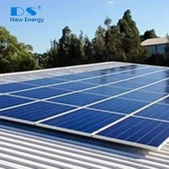
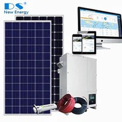
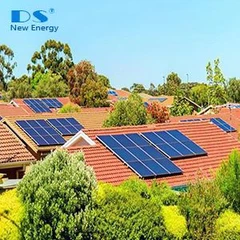
With the rapid development of solar technology, photovoltaic power generation has become one of the important green energy solutions worldwide. Photovoltaic systems play a significant role, whether on residential rooftops, industrial parks, or large-scale solar power plants. At the same time, the safety issues of photovoltaic systems are gradually gaining attention. DC arc, as an electrical phenomenon that may affect the stability of photovoltaic systems, is worth careful understanding by every practitioner and user.
1.The Meaning of DC Arc Striking
Direct current arcing, as the name suggests, refers to the phenomenon where an arc forms between contact points when the current path in a direct current circuit is suddenly interrupted.
An electric arc is a type of gas discharge phenomenon. When a gas is ionized, it forms a conductive channel, resulting in an electric arc. In photovoltaic DC circuits, when a tiny gap occurs in the circuit, the DC voltage across the gap will create an electric field within it. When the electric field strength reaches a certain level, air molecules become ionized. Air molecules are made up of atoms, which consist of positively charged nuclei and negatively charged electrons. Under a strong electric field, electrons gain enough energy to break free from the nucleus and become free electrons. These free electrons accelerate in the electric field, collide with other air molecules, ionizing more molecules, thereby creating a large number of free electrons and positive ions. This process is known as gas breakdown. Once the gas is broken down, an electric arc forms.
DC Arc Striking Process:


For direct current, since it has no zero crossing point and the current direction does not change, the arc can continuously receive energy, making it difficult to extinguish on its own.

According to the circuit connection method and the arc location, arcs can be divided into series arcs and parallel arcs (Grounding arc can be regarded as a special type of parallel arc). Series arcs usually occur within a single live conductor. Because the spacing between conductors is small and there are many conductors, the frequency of occurrence is higher; moreover, since the series arc signal is weak and easily masked by noise, it is difficult to detect and, if not addressed in time, can easily cause fires. Parallel arcs usually occur between different live conductors. Since the spacing between conductors is large and the path is complex, the frequency of occurrence is lower. Currently, protective measures such as fuses and circuit breakers can effectively control the impact of parallel arcs.

2.Causes of DC Arc Striking
2.1Connection Component Issues
Connection components are one of the most common trouble spots in photovoltaic systems and are also a major cause of DC arcing.
- Loose, oxidized, or worn connectors (such as MC4 plugs) are common problems: During long-term use, connectors may become loose due to factors such as vibration and temperature changes. Loose connectors can increase contact resistance, generating a large amount of heat when current passes through, causing the connector's temperature to rise. High temperatures accelerate the oxidation and wear of the connector, creating a vicious cycle that eventually leads to gaps, which can trigger arcing.
- Cable joint crimping is not up to standard: Insufficient crimping force or leakage can lead to poor contact at cable joints, which similarly increases contact resistance, generates high temperatures, and can consequently cause arcing.
2.2Conductor Problems
Wires are important components in photovoltaic systems for transmitting current, and their quality and condition directly affect the safe operation of the system.
- Damage to the cable insulation layer can cause a gap between the conductor and grounding bodies or metal supports, which can lead to arcing: The cable insulation may be damaged during installation or use due to factors such as mechanical damage or chemical corrosion.
- The wire may be damaged by external forces (such as rodents gnawing or mechanical friction), resulting in local exposure, which is also one of the causes of arc stretching: In some outdoor photovoltaic power stations, rodents gnawing on cables occurs from time to time.
2.3Environment and Aging Factors
Environmental factors and equipment aging are also important causes of DC arcing in photovoltaic systems.
- Prolonged exposure to high temperatures and high humidity can accelerate component aging, leading to a decline in insulation performance: In high-temperature environments, the materials of the components undergo thermal aging, causing their performance to gradually decline; in high-humidity environments, the components can become damp, affecting their insulation properties.
- Dust and corrosion build up at the connection points, which can disrupt electrical continuity and cause gap discharge: In dusty environments with strong corrosiveness, connection points tend to accumulate a large amount of dust and corrosive substances. These materials can hinder the transmission of electric current, increase the resistance at the connection points, generate high temperatures, and potentially cause arcing.
3.Detection Technology and Application of DC Arc in Photovoltaics
3.1Arc Fault Circuit Interrupter (AFCI/AFDD)

|
Parameter |
Specification |
|
Compliance Standards |
IEC/EN62606, IEC/EN61009, GB/T31143-2014, GB14048.2 |
|
Rated Working Voltage |
AC 230V / AC 110V |
|
Rated Frequency |
50Hz / 60Hz |
|
Rated Current (In) |
6, 10, 16, 20, 25, 32, 40, 50, 63A |
|
Number of Poles |
1P / 2P |
|
Rated Impulse Withstand Voltage Uimp |
4kV |
|
Rated Short-Circuit Breaking Capacity |
4.5kA |
|
Rated Tripping Current In |
10mA~500mA Adjustable |
|
Rated Non-Tripping Current Ino |
0.5In |
|
Tripping Curve |
0.5In |
|
Operation Type |
Instantaneous, Delayed, with Selectivity |
|
Leakage Type |
AC, A |
|
Adjustable Overvoltage Range |
250 - 280V |
|
Adjustable Undervoltage Range |
180 - 120V |
|
Communication Mode |
RF2.4G CAN BUS |
|
Basic Protection Functions |
Can timely interrupt power supply in case of short circuit, overload, arc and leakage faults in load supply circuits |
|
Other Functional Features |
Equipped with LED status indicator, fault memory, LED indicator function for load (>2A), leakage alarm function, capable of realizing wireless networking and energy management functions |
The function of an AFCI is to 'detect and cut off power' immediately when an arc occurs, preventing the fire from spreading.
It is usually integrated into DC combiner boxes, inverters, or circuit breakers to monitor current signals in real time. When an arc occurs, the current waveform exhibits specific high-frequency noise and distortion. The AFCI uses algorithms to detect this abnormal signal and quickly disconnects the circuit.

As shown in the current spectrum waveform above, the red indicates the occurrence of an electric arc, clearly contrasting with the blue where there is no arc.
In a typical electrical system, background random noise generally only varies noticeably at frequencies above 200 kHz. In contrast, switching controller circuits such as inverters in the electrical system typically operate at spectra below 50 kHz. Not to mention, the AC power supply signal itself is at an even lower frequency of 50/60 Hz. Therefore, by using the FFT algorithm to convert the detected cable current into the frequency domain and then analyzing the frequency band between 30 kHz and 100 kHz, it is possible to effectively distinguish between normal operation of the circuit system and abnormal arcing conditions.
Main structure
AFCI arc fault circuit breakers mainly consist of a breaker module, leakage module, power module, signal conditioning module, trip unit module, and communication interface module.
- Power module: supplies power to the relevant devices inside the AFCI/AFDD.
- Signal conditioning module: The current signal in the main circuit is passed through a line current transformer to the signal conditioning module. The module amplifies, rectifies, and filters the signal before sending it to the microcontroller for processing.
- Tripping Module: In the AFCI arc fault circuit breaker, the electromagnetic structure of the tripping module adopts a new energy-saving technology, minimizing the core losses and short-circuit losses of the switch electromagnetic system, thereby maximizing energy savings. A buffering device is added to reduce the energy impact on the electromagnetic system, improving the switch's closing performance and extending its service life. The operating mechanism of the tripping module can receive fault signals detected by the main control chip MCU and interrupt the coil circuit through controlling contacts, with the electromagnetic mechanism breaking the main circuit. After the fault is cleared, pressing the operating button resets the module.
- Communication interface module: This module allows real-time transmission of data such as current, voltage, current phase, and arc signals to the terminal computer, enabling remote monitoring.
Working principle
The main control chip MCU of the AFCI arc fault circuit breaker monitors the current signal in the main circuit in real time. When an arc fault is detected in the main circuit, the microcontroller sends a trip signal, and the trip circuit executes the trip operation.
3.2Infrared Thermal Imaging Technology

Infrared thermal imaging technology detects abnormal heating at connection points through an infrared camera, allowing potential arc risks to be identified in advance. Poor contact is often accompanied by localized high temperatures, and infrared thermal imaging can clearly display these high-temperature areas, providing maintenance personnel with an intuitive reference.
4.Protective Measures and Implementation for DC Arc Faults in Photovoltaics
4.1Standard Installation
Proper installation is the foundation for preventing DC arcing in photovoltaic systems. During the installation process, ensure that connectors and cable joints are firmly crimped to avoid loose connections. Professional tools should be used for crimping, operating with the specified force to ensure minimal contact resistance at the connection points.
At the same time, choose insulation materials that meet the standards to reduce the risk of mechanical damage. When installing cables, avoid excessive bending and stretching to prevent damage to the insulation layer.
4.2Component Selection
Choose connectors and cables that are resistant to aging and high temperatures, and especially in harsh environments, enhance the protection level of components (such as IP65/IP67). When selecting components, fully consider the environmental conditions of the photovoltaic power station, such as temperature, humidity, and corrosiveness.
For example, in photovoltaic power plants in high-temperature areas, connectors and cables that can maintain stable performance at higher temperatures should be chosen; in highly corrosive environments such as coastal areas, components with corrosion resistance should be selected.
4.3System Design Optimization
System design optimization is crucial for preventing DC arcing in photovoltaic systems. During the design process, it is important to avoid excessively high DC voltages (which must comply with safety standards), reduce long cable runs, and minimize the likelihood of gap discharge.
Reasonably plan the arrangement of photovoltaic modules and the routing of cables, aiming to minimize cable length and reduce the number of bends and joints in the cables. At the same time, appropriate protective devices should be installed, such as fuses, circuit breakers, and arc fault protection devices, to promptly cut off the power in case of any abnormalities in the circuit.