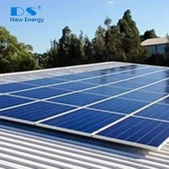
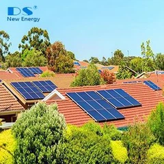
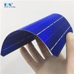
Solar PV systems comprise of a number of solar panels wired into arrays depending on the electric power demand from each of those panels, which in turn, composed of many solar PV cells that are the essential units involved in capturing energy from the sun and converting them into electricity. Now, if a shadow falls even only on one part of the solar panel in your array, the output from the complete system may be potentially compromised, this can be referred to as shading of PV panels.
Picture showing difference in output from shaded and unshaded solar panel

For better understanding
Consider a string of panels as a piece of pipe, and the solar energy is like water flowing through that pipe. In conventional solar strings, a shade is something that blocks that flow. If, as an example, shade from a tree or a chimney falls on even one in all the panels within the string, the output of the whole string reduced to just about zero for as long as the shadow sits there. If there’s a separate, unshaded string, however, this string can still turn out power as per usual.


Graphical representation of effect of shading on solar system

What are the factors causes shading?
Shading, typically caused because of clouds, environmental obstructions such as trees or nearby buildings, self-shading between panels in parallel rows, dirt, dust and different other trash like bird droppings, etc. These shading effects are also static as a result of the position of the obstruction or in some cases dynamic, as an example, a shadow cast by moving clouds.
How does it affect the performance of solar power system?
Solar panels are connected into series-parallel combination depending on the inverter input voltage range. If shade from a tree or chimney is falling even on one panel of the string, the output of the whole string will nearly be zero for the period of the shade. This is because the panels are wired together in such a way that the output is reduced to a level of current passing through the weakest panel. If there’s a separate, unshaded string, it’ll still turn output power as usual. The impact of shade on the whole system depends on however the panels are wired together.

How to tackle shading problem?
Positioning of PV systems

Before installing a solar PV system you must do a careful analysis of the site considering all time of the day for all seasons of the year to avoid shade. A nearby growing tree or building that may come up in future also need to be considered before finalizing the location for PV System.
Bypass Diode
Bypass Diodes to lower effect of shading
The destructive effects of hot-spot heating may be circumvented through the use of a bypass diode. A bypass diode is connected in parallel, but with opposite polarity, to a solar cell as shown below. Under normal operation, each solar cell will be forward biased and therefore the bypass diode will be reverse biased and will effectively be an open circuit. However, if a solar cell is reverse biased due to a mismatch in short-circuit current between several series connected cells, then the bypass diode conducts, thereby allowing the current from the good solar cells to flow in the external circuit rather than forward biasing each good cell. The maximum reverse bias across the poor cell is reduced to about a single diode drop, thus limiting the current and preventing hot-spot heating. The operation of a bypass diode and the effect on an IV curve are shown in the animation below.
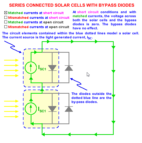 Current flow for two cells in series and the effect of a bypass diode. The animation progresses automatically from one condition to another.
The effect of a bypass diode on an IV curve can be determined by first finding the IV curve of a single solar cell with a bypass diode and then combining this curve with other solar cell IV curves. The bypass diode affects the solar cell only in reverse bias. If the reverse bias is greater than the knee voltage of the solar cell, then the diode turns on and conducts current. The combined IV curve is shown in the figure below.
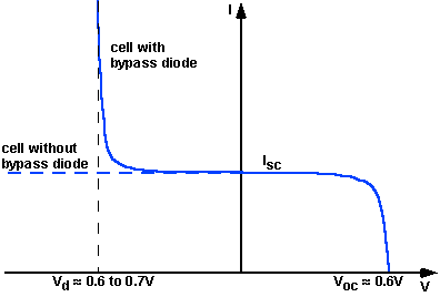
IV curve of solar cell with bypass diode.

Preventing hot-spot heating with a bypass diode. For clarity, the example uses a total of 10 cells with 9 unshaded and 1 shaded. A typical module contains 36 cells and the effects of current mismatch are even worse without the bypass diode, but are less important with the bypass diode. The animation moves automatically. You do not need to click to continue.
In practice, however, one bypass diode per solar cell is generally too expensive and instead bypass diodes are usually placed across groups of solar cells. The voltage across the shaded or low current solar cell is equal to the forward bias voltage of the other series cells which share the same bypass diode plus the voltage of the bypass diode. This is shown in the figure below. The voltage across the unshaded solar cells depends on the degree of shading on the low current cell. For example, if the cell is completely shaded, then the unshaded solar cells will be forward biased by their short circuit current and the voltage will be about 0.6V. If the poor cell is only partially shaded, the some of the current from the good cells can flow through the circuit, and the remainder is used to forward bias each solar cell junction, causing a lower forward bias voltage across each cell. The maximum power dissipation in the shaded cell is approximately equal to the generating capability of all cells in the group. The maximum group size per diode, without causing damage, is about 15 cells/bypass diode, for silicon cells. For a normal 36 cell module, therefore, 2 bypass diodes are used to ensure the module will not be vulnerable to "hot-spot" damage.

Bypass diodes across groups of solar cells. The voltage across the unshaded solar cells depends on the degree of shading of the poor cell. In the figure above, 0.5V is arbitrarily shown.
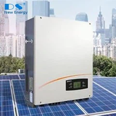
String inverter with MPP tracking capability
Maximum Power Point Tracking (MPP Tracking or MPPT) technology is now a standard among string inverter manufacturer. String inverters with MPP Tracker are able to squeeze the most usable energy possible out of a string of solar panels (even when shaded) by adjusting the input voltage. In a nutshell, an MPP Tracker helps to minimize output losses associated with partial shading and other output mismatches. Inverters without MPPT technology lose the output from the weaker string when it passes below the desired output threshold.

Micro Inverter and power optimizers
Both Microinverters and power optimizers are used to overcome the problem of partial shading. It allows every solar panel to work individually so that the system energy production is not disproportionately affected by just one or two shaded panels.


Different types of solar shadings
There are different types of solar shadings, depending on the objects that create the shade.
Temporary shading
Temporary shading includes shading that is the result of clouds, bird droppings, dust or fallen leaves.
Shading resulting from the building
Shadings resulting from the building is critical as it involves direct shadows. Examples of this type of shading are chimneys, lighting conductors, satellite dishes, antennae, roof and façade protrusions, offset building structure, roof superstructure just to name a few.
Shading from the location
The shading from the location comes from the building’s surrounding. There could be trees or bushes, cables running over the buildings, neighboring building or distant buildings which could equally cause horizon darkening.
Self-shading
With rack-mounting systems, self-shading of the modules may be caused by the row of the modules. In these cases, it is necessary to optimize the tilt and the separation between the module rows.
Direct shading
Direct shading can cause high losses of energy as the proximity to the shadow-casting object to hinder the PV solar panel to catch the light.