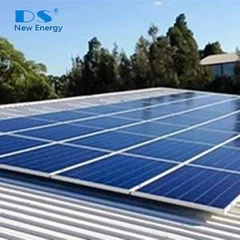
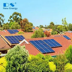


Application Scenarios
•1. Regions without grid power or unstable grid supply, like remote countryside, islands, isolated places.
•2. Schools, hospitals and other public utilities needs stable & constant energy supply.
•3. Factories wish to restructure energy consumption.
•4. Regions with step electricity rate or peak-valley rate policy, to store the energy at low rate hours and using at high rate hours.
•5. Individuals or entities who wish to be independent at energy supply to be less depending on grid power.
System Diagram

System Diagram Block

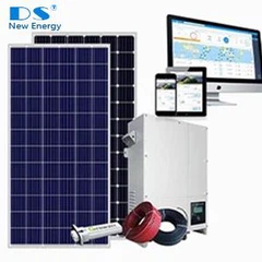
Electrical Component List
| Item | Description | Qty. | Unit |
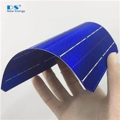
| Solar panel 100kW (100kw to 145kw) | Monocrystalline silicon PERC Half-Cut 450W | 228 | pcs |
| Mounting structure | Rooftop mounting structure or ground mounting structure for 228 panels, aluminum or hot-dip galvanized steel structure optional | 1 | pcs |
| Combiner box | 1000V DC combiner box (optional 2 to 20 strings) 12 in 1 output, 19pcs panel each string |
1 | pcs |
| Hybrid inverter 100kw | HPS 100 Max. PV input 145kW, parallel function |
1 | pcs |
| LFP Battery 145.92kWh (116.74kWh available at 80% DOD) |
Battery module 38.4V, 200Ah, 7.68kWh | 19 | pcs |
| Battery Rack with BPU | Battery Rack With BPU (battery management system) | 1 | set |
| Monitoring & Management system | EnerLog Monitoring datalogger | 1 | set |
| PV cable | 4mm2, Red /Black | 2000 | mtr |
| PV Connector | MC4 compatible | 100 | pcs |